.png)
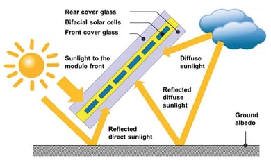
Unlike conventional PV modules that convert only front-side irradiance into electrical power, bifacial modules convert both front- and back-side irradiance into electricity. While the additional rear-side irradiance improves plant performance in terms of energy production, revenue and levelized cost of energy (LCOE), industry standards and best practices for predicting and quantifying these gains largely remain a work in progress. Here, I correct three common misconceptions related to bifacial gain in the real world.
Misconception #1: The Engineer of Record Defines Bifacial Gain
During the project design phase, the engineer of record must determine a percentage of bifacial gain that it will use for sizing conductors and overcurrent protection. As with many other engineering analyses, this bifacial gain estimate includes a margin of safety. This conservative estimate is based on potential worst-case scenarios that do not reflect typical plant operating conditions. As a result, using the bifacial gain percentage defined by the engineer of record will overstate bifacial gain and plant performance in the real world.
Reality: Bifacial gain is not an input; it is a result.
From the perspective of the owner’s engineer (OE), bifacial gain is not a simple input to a software model but rather the result of multiple design and engineering decisions related to the balance of system (BOS) components. In order to estimate bifacial gain in the field, an OE must account for the impact of each of these design decisions. For example, what is the racking type and configuration? What is the height of the array or the ground coverage ratio?
Each of these decisions will yield a result. For bifacial gain purposes, a taller array is better than a shorter array; a wider array spacing is better than a narrow spacing and so forth. While these relationships are often straightforward, they cannot be ignored. In order to predict bifacial gain and system production, the software model used to predict plant performance needs to characterize the impacts of BOS design and engineering decisions.
Misconception #2: The Design Drawings Determine Bifacial Gain
While design and engineering decisions have a major impact on bifacial gain, construction details are equally important. Wire management details and combiner box placement are potential sources of shade that can further erode bifacial gain. If the construction details in the field do not match those in the plan set, the actual bifacial gain will not match the theoretical bifacial gain.
Reality: Construction details and rear-side shading from BOS matters.
It is very important that an owner’s engineer review and approve a so-called golden row, both on paper and in the field. This reference row should define wire management practices that minimize rear-side shading; it should also establish benchmarks for build quality, especially for tracker systems, which have moving parts. Once construction commences, the quality assurance and quality control (QA/QC) team can use this reference row as a template for its QA/QC activities to ensure that the as-built conditions match the planset and the reference row. Standardizing these construction details and practices will not only improve plant production but also the confidence of the production model, both in terms of operational considerations and rear-side shading expectations.

Courtesy Hukseflux
Seasonality & Location
The time of year and project location are critical to capacity testing success. ASTM E2848 defines a range of acceptable testing conditions, as well as certain disqualifiers. These grounds for disqualification relate to low or high irradiance levels and the presence of shade or inverter power limiting. Note that these are often interrelated. When irradiance is low, you tend to have shade based on the time of day or year. Similarly, when irradiance is high, the system is most likely to experience inverter power limiting and power curve clipping.
Note that the time required to conduct a passing test is highly variable based on the project location. This is especially true in winter when you might have only eight hours of sunlight per day. If you have to throw out two hours in the morning and two hours in the evening due to low irradiance or shade, your window for conducting a capacity test is down to four hours. If you have to throw out two hours in the middle of the day because of clipping, that leaves you with two hours—or eight 15-minute interval data points—per day.
Given that you need 50 valid data points, you may need a week of perfect weather to pass a capacity test. While that might be possible in California, Colorado or Nevada, winter commissioning is likely impractical in the Midwest or the Northeast. If the weather is unlikely to cooperate, it is better to postpone capacity testing to a later date. It is best to plan and contract for this contingency in the event that construction schedule delays push performance testing into the November to January timeframe.
![]()
Courtesy The Coloradoan
Technology & Design
Last but not least, you may need to adapt your capacity test methods to account for technology and design details, such as bifacial modules or high dc-to-ac ratios. While it is possible to run capacity tests under these circumstances, you will need to plan for it and implement a different strategy.
While the ASTM E2848 standard does not specifically address bifacial modules, for example, there are ways to work around it. Specifically, you have to add a back-of-module POA sensor in order to model these new capacity contributions. In a bifacial system, in other words, the total POA irradiance for capacity testing purposes is the sum of the front-side POA irradiance plus the rear-side POA irradiance. By accounting for the rear-side irradiance in the regression equation, you can adapt the test procedure to accommodate this technology.
To adapt to a high dc-to ac ratio, we want to modify system operation to fit the test criteria. Note that this requires a prequalification step. If the inverters are power limiting more than 50% of the day, the system probably qualifies as having a high dc-to-ac ratio. In this case, you should consider some means of modifying system operation. If it is a tracker system, you could defeat the trackers and run the system flat. Alternatively, you could remove half of the dc capacity, effectively shutting off half or the dc strings and conducting capacity tests on one half of the array at a time. Note that whichever option you pick, you will need to adapt your model to reflect this temporary performance condition.
Looking to partner with a full-service engineering team that specializes in solar and energy storage applications? Contact Pure Power Engineering to learn more about our engineering services.
